
The makemap tool uses rules written in a small XML-based language to control the import of data from OSM and other sources. The idea is that an input data set is supplied containing a set of attributes and values (a row in the map database), and a program made up from a series of statements uses it to create one or more output map objects.
makemap uses a standard set of rules. You can write them out using makemap (see makemap's usage message for details) and edit them to create your own rules.
Thus a single input data set (database row) can create more than one map object, but the converse is not true.
The program is executed in its entirety once for each input data set.
Note: this file type and rules system are obsolete. Use the newer system (.makemap files) instead. This documentation is provided to help understand old osm_to_ctm1 files.
Here are two maps of the same area drawn using different style sheets.
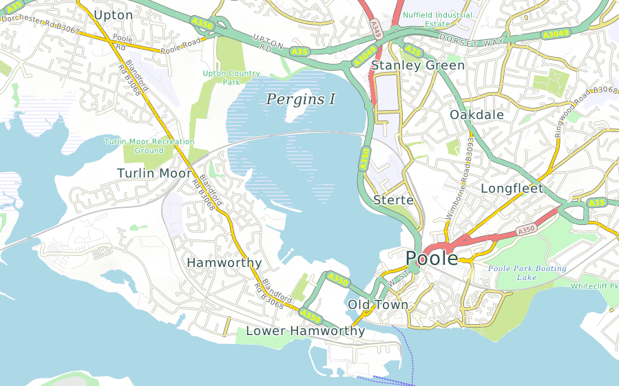
Above: Poole in southern England using the standard style sheet.
Dimensions are specified using numbers followed by optional units. A number without a unit refers to pixels. Sometimes units are not allowed, as for example in opacity levels, which are dimensionless. Where units are allowed, you can use any of the following:
- pt: printer's points of exactly 1/72in (sometimes called PostScript points).
- pc: printer's picas of 12pt.
- cm: centimeters.
- mm: millimeters.
- in: inches.
- m: map meters; that is, meters at the scale of the map, converted to pixels using the current map projection.
- %: a percentage of some value depending on context; for example, in the context of a road, percentages refer to the width of the road, allowing you to specify that a road name is 75% of the width of the road.
Dimensions can optionally be followed by limits: minimum and maximum values. For example, it is useful to specify a label size in map meters, but clamp it to a certain range of sizes, avoiding lettering that is too small to read, or so large as to be ugly and obtrusive. For example:
{code}
font-size="300m,8pt,24pt"
{lang}cpp{highlight}{end-code}
sets a label size to 300 map meters but clamps it to the range 8pt...24pt. It is legal to omit the third (upper) limit, as in:
{code}
width="45m,2pt"
{lang}cpp{highlight}{end-code}
Limits must not be negative. A minus sign can occur only before the main dimension; if so, the dimension, with its limits, is evaluated as if it was positive, then negated.
Colors are RGBA (red, green and blue components plus an 'alpha' or opacity level), and can be specified in these ways:
- Hexadecimal 24-bit RGB, in the form #RRGGBB, where each group of two hex digits is an 8-bit intensity value. An opacity value of 255 (fully opaque) is used.
- Hexadecial 24-bit RGB using three digits only: #RGB; the digits are treated as #RRGGBB
- Hexadecimal 32-bit RGBA, in the form #RRGGBBAA, where the first three groups of two hex digits are the red, green and blue intensity levels and the last (AA) is the alpha or opacity value, where 0 = transparent and 255 = opaque.
- Hexadecimal 32-bit RGBA using four digits only: #RGBA; the digits are treated as #RRGGBBAA
- As an SVG color keyword. SVG (the W3 Scalable Vector Graphics standard) defines over a hundred keywords for colors, including all the common names and many unusual ones like 'khaki' and 'teal'.
Fonts are specified using a subset of the CSS font style attributes. For details see Labels.
Labels in style sheets
The <label> section in a <layer> section tells CartoType to draw a label and defines its style, including font attributes.
You can have up to two <label> sections in a <layer>. That enables you to draw both a highway shield with the highway reference, and an ordinary name along the road, for example. Use <labelAttrib> to select the correct name for each label, if using more than one.
The <label> attributes, in alphabetic order, are:
<scale> and <zoom> sections in style sheets
You will nearly always want your maps to look different at different scales. Some objects will not appear at some scales, and other will be drawn very differently. For example, minor roads may not appear at small scales, and city names may be suppressed or drawn as a faint overlay at large scales.
The easiest way to make this happen is to use <scale> sections:
{code}
<scale min='m' max='n'>
...
</scale>
{lang}xml{highlight}{end-code}
with any balanced XML you like inside them.
It is often necessary to enable or disable parts of a style sheet, or make them dependent on run-time parameters. While it's possible to solve the problem using several different style sheets, it is much easier to put everything into one style sheet and select different features at run-time using conditional compilation controlled by parameters set by the application.
You can select any part of a style sheet (that is, any balanced XML) using
{code}
<if exp="expression"> ... </if>
{lang}cpp{highlight}{end-code}
Structure of a CartoType style sheet
Summary:
{code}
<?xml version="1.0" encoding="UTF-8"?>
<CartoTypeStyleSheet background='lightblue' border='lightgrey' labelFormat=';int_name;name:en;ref+{font-style:italic}" ("name:en")"' landLayer='outline' name='standard style'>
<defs> ... </defs>
<layer name="park"> ... </layer>
<layer name="river"> ... </layer>
<layer name="road"> ... </layer>
<layer name="other-layer"> ... </layer>
...
<labelLayer/>
</CartoTypeStyleSheet>
{lang}xml{highlight}{end-code}
Levels of map objects
Most mapped objects are at ground level, but often it is useful to distinguish between various vertical levels, to allow the map to display objects in layer order.
CartoType uses 16 different levels. Ground level is 0, lower levels range from -8 (lowest) to -1, and higher levels range from 1 to 7 (highest).
Levels of map objects
The level is stored in the FeatureInfo attribute of a map object, which has an attribute called Level. The level of an object cannot be changed in the style sheet, but may be tested in a style sheet expression by using the special variable @level.
You can create CartoType maps (CTM1 files) containing array objects. These are effectively textures in computer graphics terms: that is, they are rectangular bitmaps which can be projected on to the map and rendered in various ways.
The most common standard layers created in CTM1 files by the tool generate_map_data_type1 are called terrain-shadow and terrain-height-feet.
Terrain shading using the terrain-shadow layer
The terrain-shadow layer contains an eight-bit opacity (alpha) value for each sample, representing the light intensity for a simulated sun in the south-west. You draw it like this, giving a color value to be used when drawing the shadow. You can provide an opacity value as well. For example:
{code}
<layer name='terrain-shadow'>
<shape fill='#446' opacity='0.75'/>
</layer>
{lang}xml{highlight}{end-code}
gives light greyish-green terrain shading.
The <defs> section
Objects used more than once can be defined in a <defs> section. An objects must be defined before any layers in which it is used. The following types of objects can be defined in the <defs> section: macros, hachures, icons, patterns and strings.
Macros
Macros define named sections of a style sheet for re-use multiple times (full description here).
Hachures
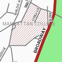
The hachure used in the example to the right is specified like this:
{code}
<hachure id="other-area-shading" width="1pt" interval="4pt" color="brown" opacity="0.4"/>
{lang}xml{highlight}{end-code}
Style sheet macros and variables
Style sheets can get very big. Two ways to save space are described here.
Macros
Macros are predefined pieces of the style sheet which can be referenced by name. You define macros in the <defs> section like this:
{code}
<defs>
<macro id='minor-road-label'>
<scale max='40000'>
<label case='assume-title' color='dimgrey' font-size='75%,5pt,12pt' glow='white' glowWidth='7%,0.5pt' priority='-2' wrapLines='0'/>
</scale>
</macro>
<macro id='standard-tunnel'>
<scale max='75000'>
<tunnel dashArray='1.5,1.5' fade='0.3'/>
</scale>
</macro>
</defs>
{lang}xml{highlight}{end-code}
The <layer> section
A layer is a named set of map objects of a common type, like roads, parks, or stations. Layers are drawn in the order in which sections appear in the style sheet. The <layer> attributes are:
- name: the name of the layer, which must match the name stored in the map data file or database
- road: if 'true' or 'yes', this is a road layer. Setting the road attribute allows layers to be drawn in appropriate order: roads, including tunnels, are drawn after (on top of) objects in earlier layers.
Displaying highlighted routes, pushpins, user-created data and other auxiliary data
CartoType applications that do navigation or route-finding need to highlight the current route, display points of interest and addresses selected by the user, and draw other temporary, fast-changing or custom data.
You can do this in a completely flexible way using an auxiliary map database supplied to CartoType at map drawing time. For example, to highlight a route, you could create a memory-resident map database (using the class CMemoryMapDataBase), add the layer "route" to it, and arrange for this database to contain one or more line objects representing the current route, if any.
You then add a layer section for the "route" layer to the style sheet, in a convenient place: probably after all other ordinary layers but before <labelLayer/>.
When a map is drawn and an auxiliary database is supplied as well as the main database, for every layer in the style sheet both databases are searched for matching objects. Objects from the main database are drawn first, then objects from the auxiliary database.
The <labelLayer> section: a special layer for icons and labels
All icons and labels are collected and drawn as a separate layer, which is drawn when the <labelLayer> section is interpreted. Icons are drawn immediately before labels. The <labelLayer> tag has no attributes, so you just place
<labelLayer/>
in the style sheet, at the same level as other layers. Normally it is the last item in the style sheet.
You can achieve various special effects by using more than one <labelLayer/> tag. Each label layer draws all the icons and labels that have been stored since the last label layer if any. One application for this feature is to draw icons and labels for routing information independently of all others, and overlapping them.
The <shape> element in a <layer> controls the drawing of polygons. The <shape> attributes are
- border: the color used to draw the border; omit this if no border is wanted; if it is specified, but borderWidth is omitted, the border is drawn one pixel wide.
- borderWidth: the width of the border. The width may not be a percentage, because there is no obvious value it could be a percentage of.
- borderOffset: the amount by which the border is inset (if positive) or moved outwards (if negative).
- dashArray: a dashed border can be drawn by supplying a list of numbers giving the lengths of the filled-in sections and the gaps between them, in units of the width of the border (given by the borderWidth attribute). For example, the value '1,2' specifies dashes one unit long and gaps two units long. The list of numbers can be any length.
- fill: the color used to fill the polygon; omit this if the polygon is not to be filled.
- height (legal values are 'yes' and 'no'): if 'yes', any suitable map object attributes are used to draw the building in 3D if required. These attributes are _t (top in meters), _b (bottom in meters) and any attribute starting with _roof:.
- insetBorder (legal values are 'yes' and 'no'): if 'yes', the border is inset by half its width, making it fit inside the polygon.
- opacity: the opacity of both the fill and border colors. To set the fill and border opacity values separately, use the #RRGGBB or #RRGGBBAA form for specifying the colors.
- smooth (legal values are 'yes' and 'no'): if 'yes', the polygon is smoothed.
Example:
{code}
<shape fill="lightgray" border="darkgray" borderWidth="10m" opacity="0.5"/>
{lang}cpp{highlight}{end-code}
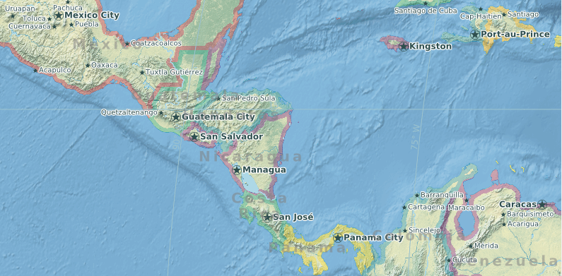
Here is a map using inset borders (insetBorder='yes') for national boundary polygons:
The <line> section in a <layer> controls the drawing of lines, the most important of which are roads. Some attributes apply only to roads. The <line> attributes are
- fill: the color used for the interior of the line
- border: the color of the borders of the line
- centerLine: (for roads only) the color of the center line of a road; used for major divided highways; center lines are drawn only if the road is marked as divided in the data
- width: the width of the line
- borderWidth: the width of the borders; percentage values refer to the width of the line
- centerLineWidth: (for roads only) the width of the center line; percentage values refer to the width of the road
- opacity: the opacity of all features - line, border and center line. To set opacity values separately use the #RRGGBB or #RRGGBBAA form for specifying the colors
- antiAlias: (allowed values: "true" or "false") if true (the default value) use anti-aliasing to draw the line and its border more smoothly.
- dashArray: a dashed line can be drawn by supplying a list of numbers giving the lengths of the filled-in sections and the gaps between them, in units of the width of the line. For example, the value '1,2' specifies dashes one unit long and gaps two units long. The list of numbers can be any length.